
Screen IC Transfer Tips for iPhone 13 Pro, 14 Pro, and 15 Pro
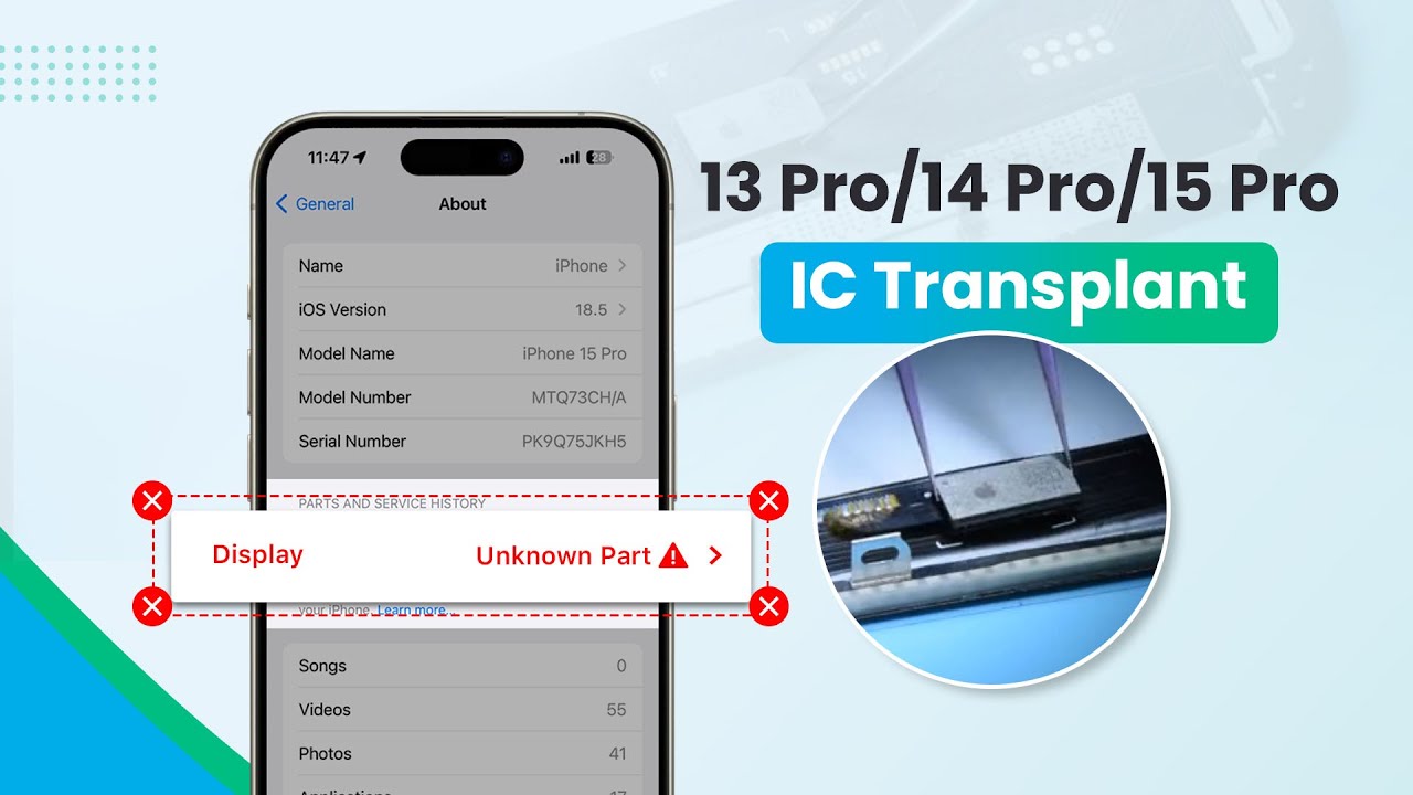
Screen IC transfer is a critical skill for technicians working on iPhone 13 Pro, 14 Pro, and 15 Pro models. With the introduction of iOS 18, Apple has eased restrictions on screen part pairing, but the ability to clear the "unknown part" alert remains essential to meet diverse repair needs. This step-by-step guide from REPART will walk you through the process of transferring the screen IC using specialized tools and techniques to ensure a successful repair.
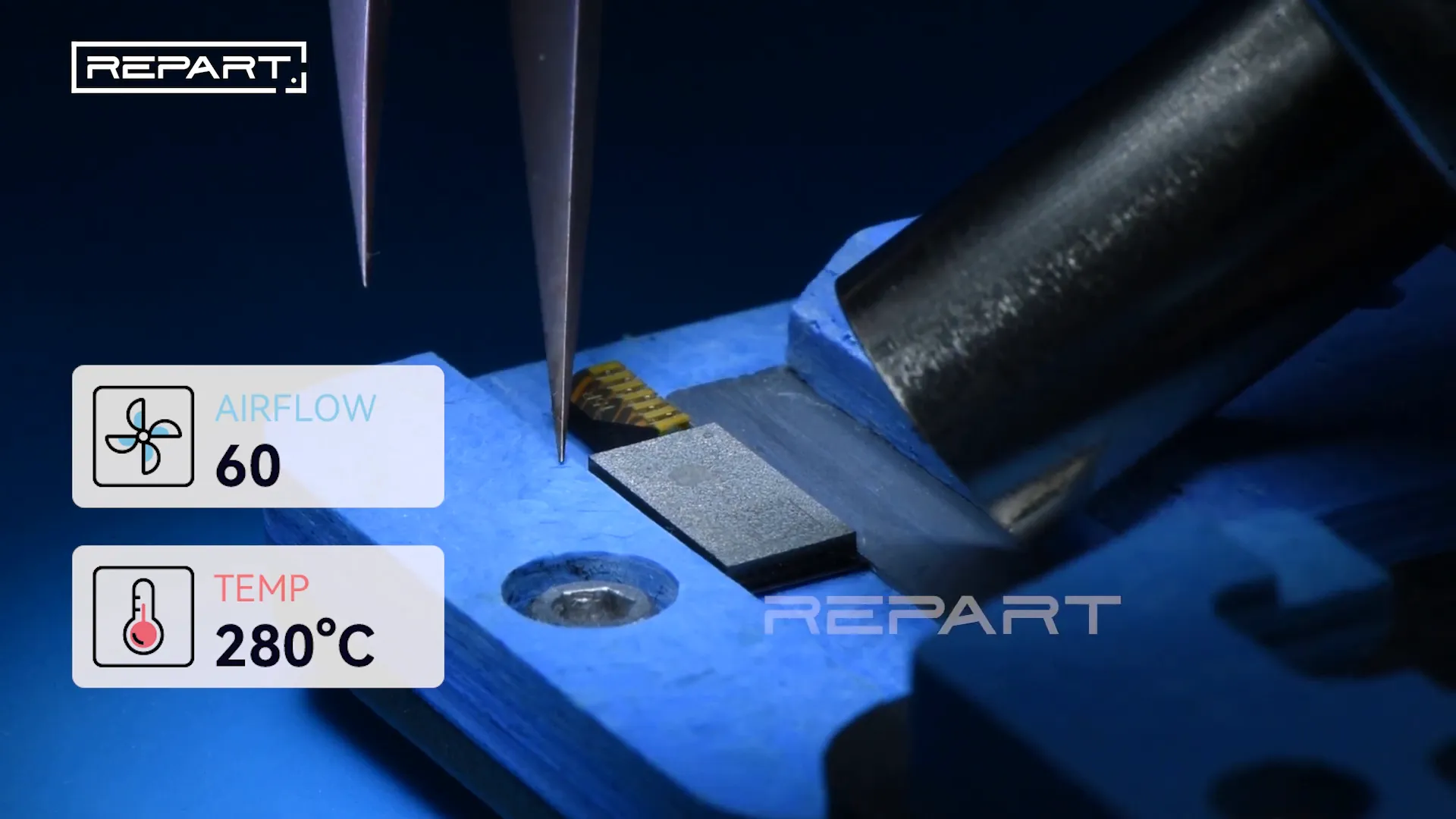
Step 1: Prepare the Hot Air Gun and Heat the IC
Begin by setting your hot air gun to 280°C with an airflow speed of 60. Hold the nozzle approximately 1 centimeter away from the IC and apply even heat for about 6 to 10 seconds. This precise heating softens the solder under the IC, preparing it for the next steps.
Step 2: Apply Medium-Temperature Solder Paste to Form Solder Balls
After heating, apply medium-temperature solder paste evenly on the IC pads. This step is crucial as it helps in forming solder balls on the IC, which will facilitate a strong and reliable connection during reflow.
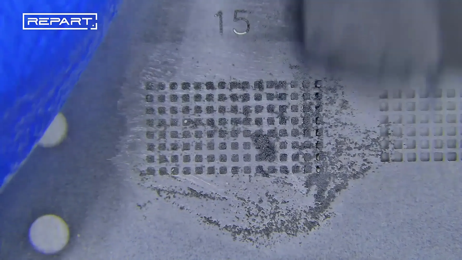
Step 3: Reflow the Solder Balls with Hot Air Gun
Use the hot air gun set at 280°C again to reflow the solder paste, allowing the solder balls to take shape beneath the IC. This ensures the IC is ready for precise alignment and soldering onto the additional soft flex cable.

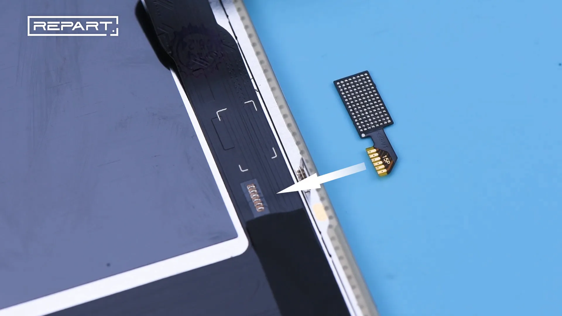
Step 4: Prepare the Additional Soft Flex Cable
The next step involves using the additional soft flex cable that comes with the REPART screen. First, apply flux on the pads of this soft flex cable to improve solder flow and adhesion.
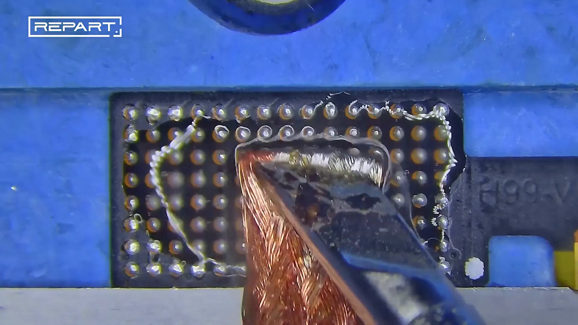
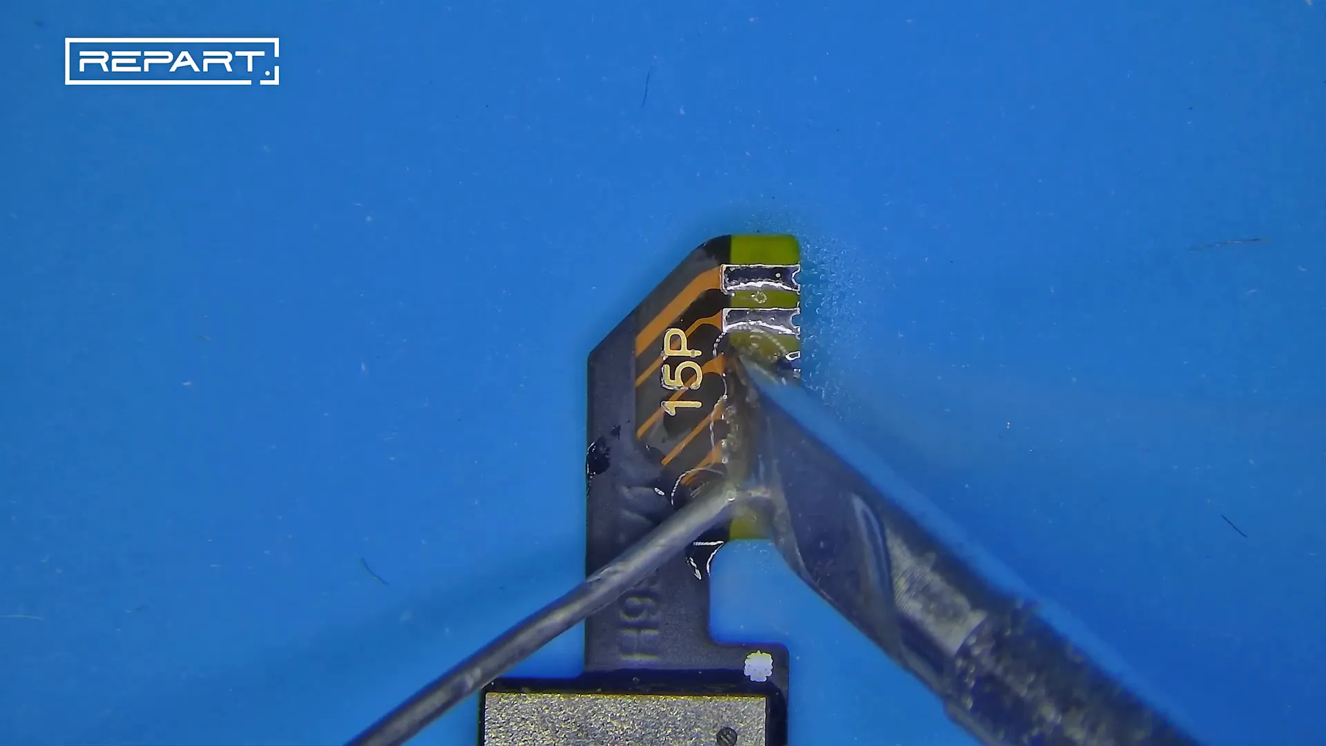
Step 5: Remove Old Solder from Soft Flex Cable Pads
Using a soldering iron heated to 390°C and a desoldering braid, carefully remove any existing solder from the pads on the additional soft flex cable. This ensures a clean surface for soldering the IC.
Step 6: Reapply Flux and Align the IC
Once the pads are clean, apply flux again on the soft flex cable pads. Then, align the IC carefully on top of the soft flex cable, ensuring the solder balls are properly positioned for reflow soldering.
Step 7: Solder the IC to the Additional Soft Flex Cable
Using the hot air gun set at 280°C with airflow speed 60, reflow the solder balls to solder the IC onto the additional soft flex cable. This step requires steady hands and precision to ensure a perfect bond without damaging the components.
Step 8: Apply Medium-Temperature Solder Wire on Soft Flex Cable Joints
To reinforce the solder joints on the additional soft flex cable, use medium-temperature solder wire to carefully touch up the connections. This adds mechanical strength and electrical reliability.
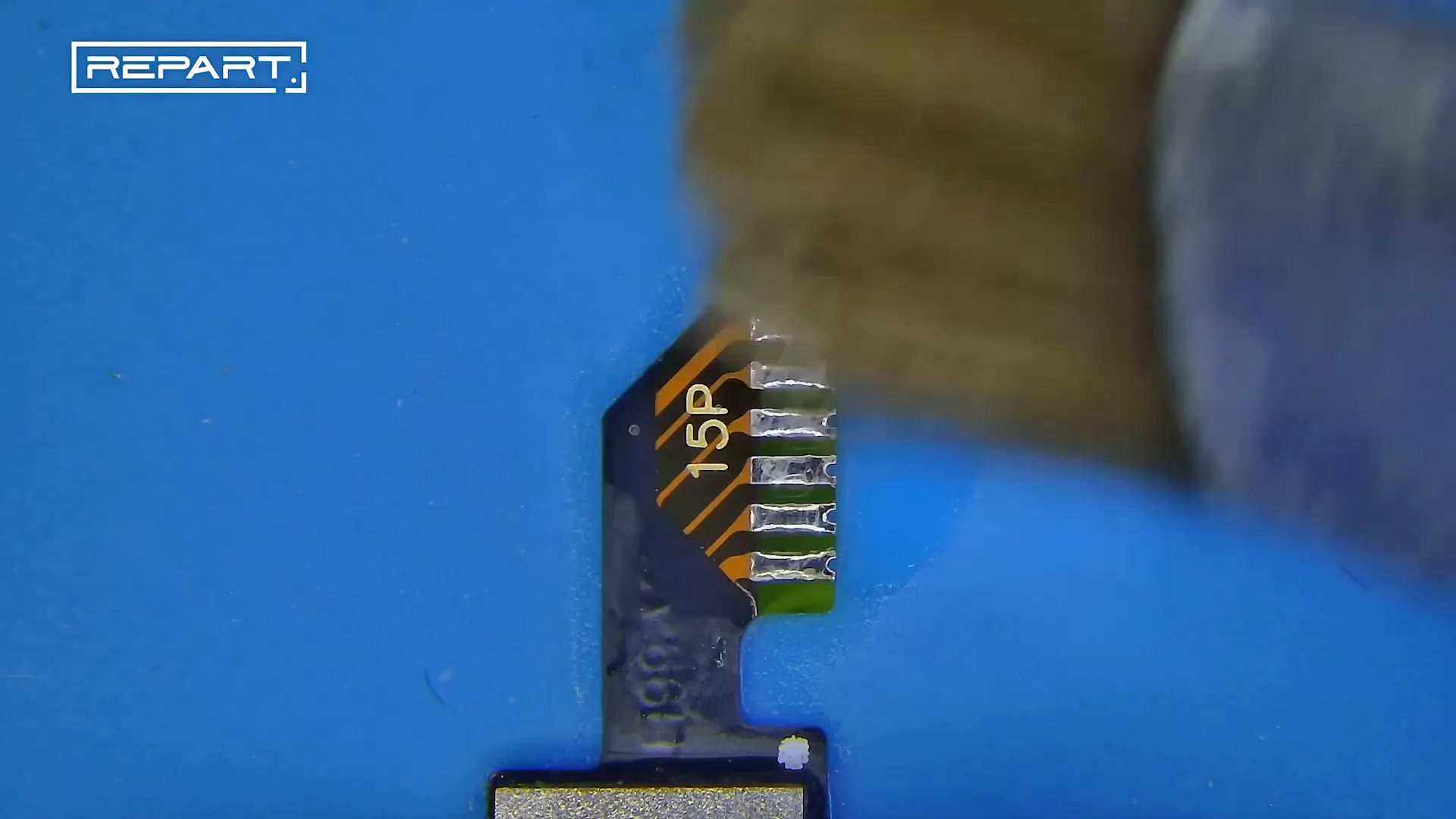
Step 9: Clean Residual Flux with PCB Cleaner
After soldering, clean the residual flux from the soft flex cable using a PCB cleaner. Removing flux residues prevents corrosion and potential short circuits.
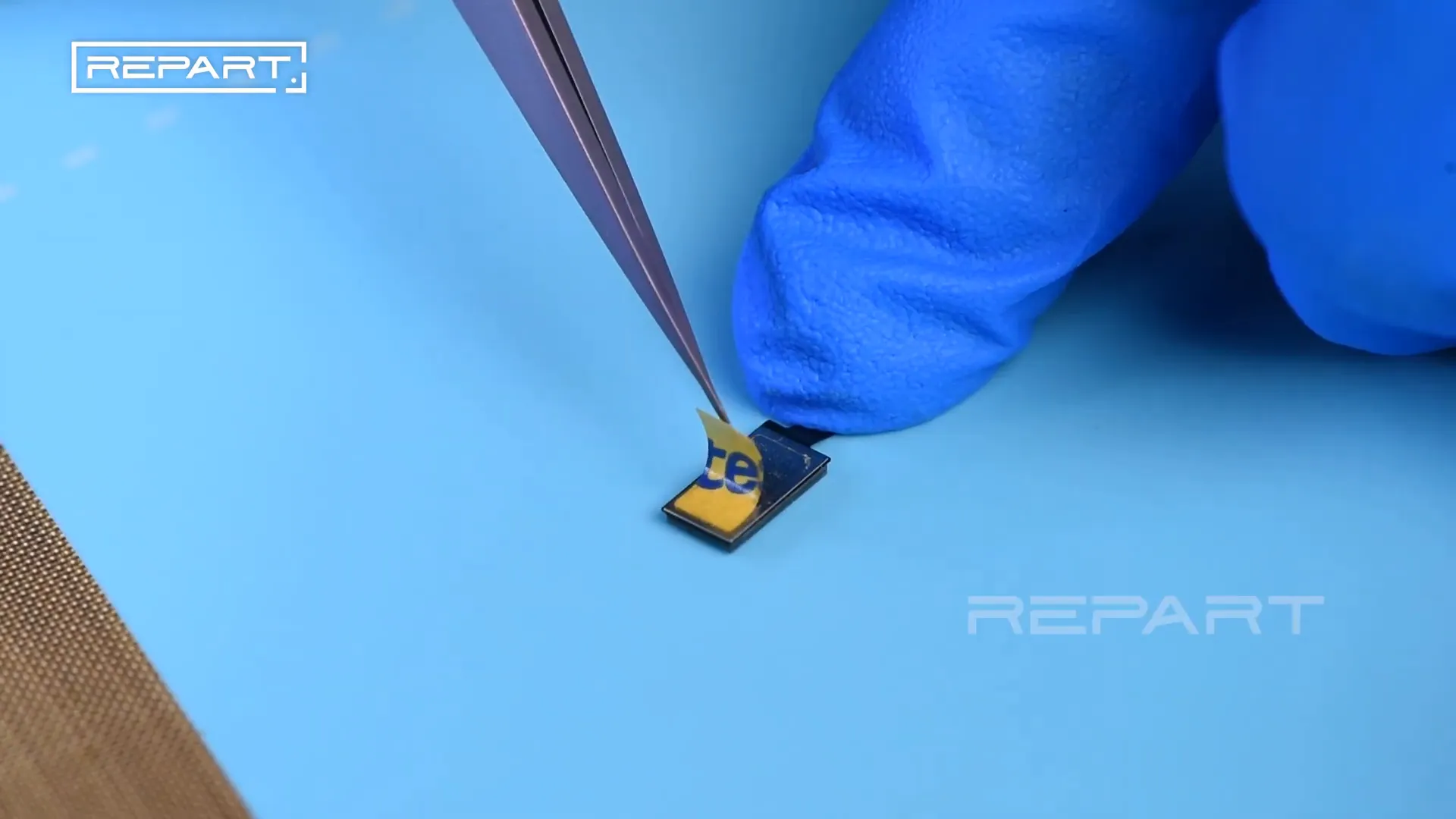
Step 10: Remove Release Film from the Back of the Pad
Peel off the release film from the back of the pad on the additional soft flex cable. This step exposes the adhesive surface needed to connect the flex cable to the REPART screen.
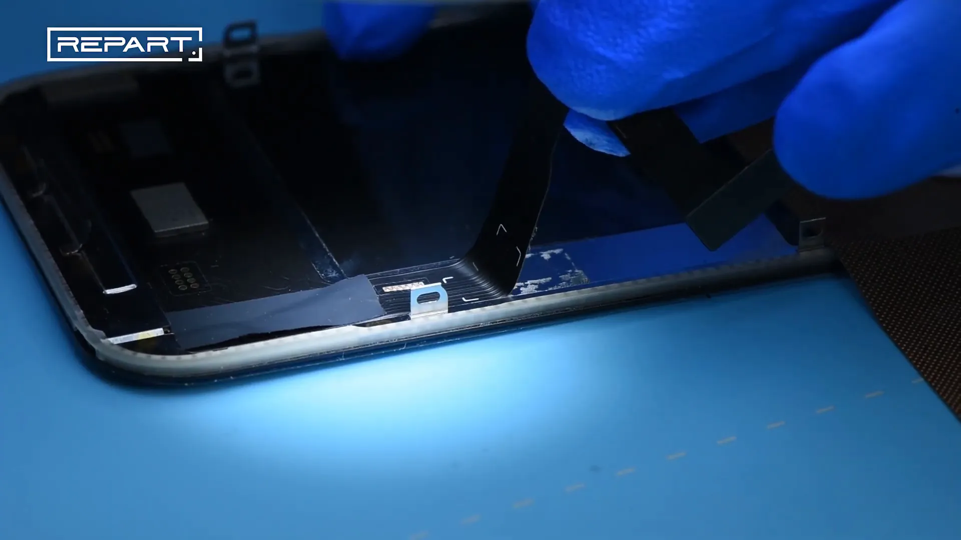
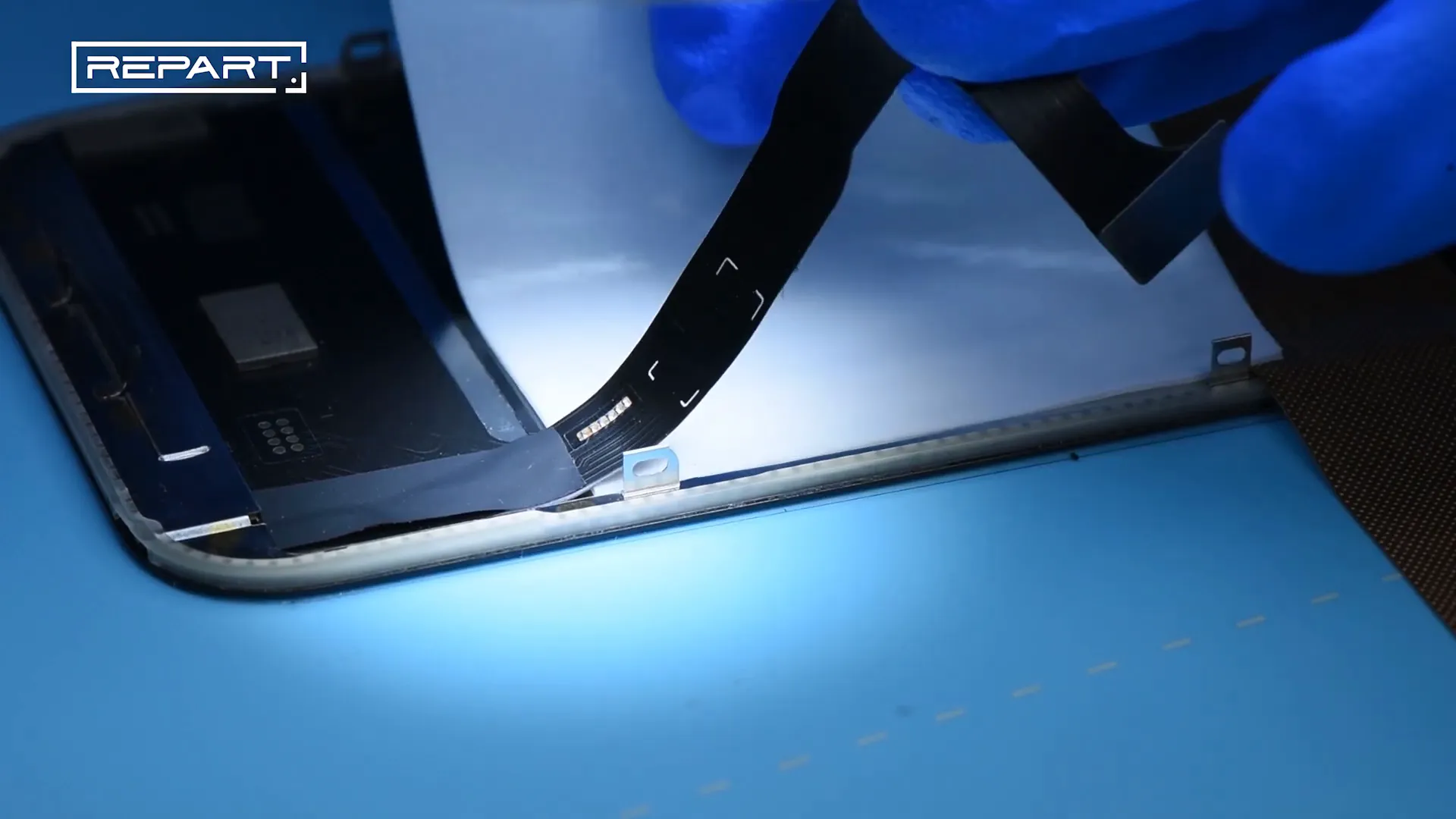
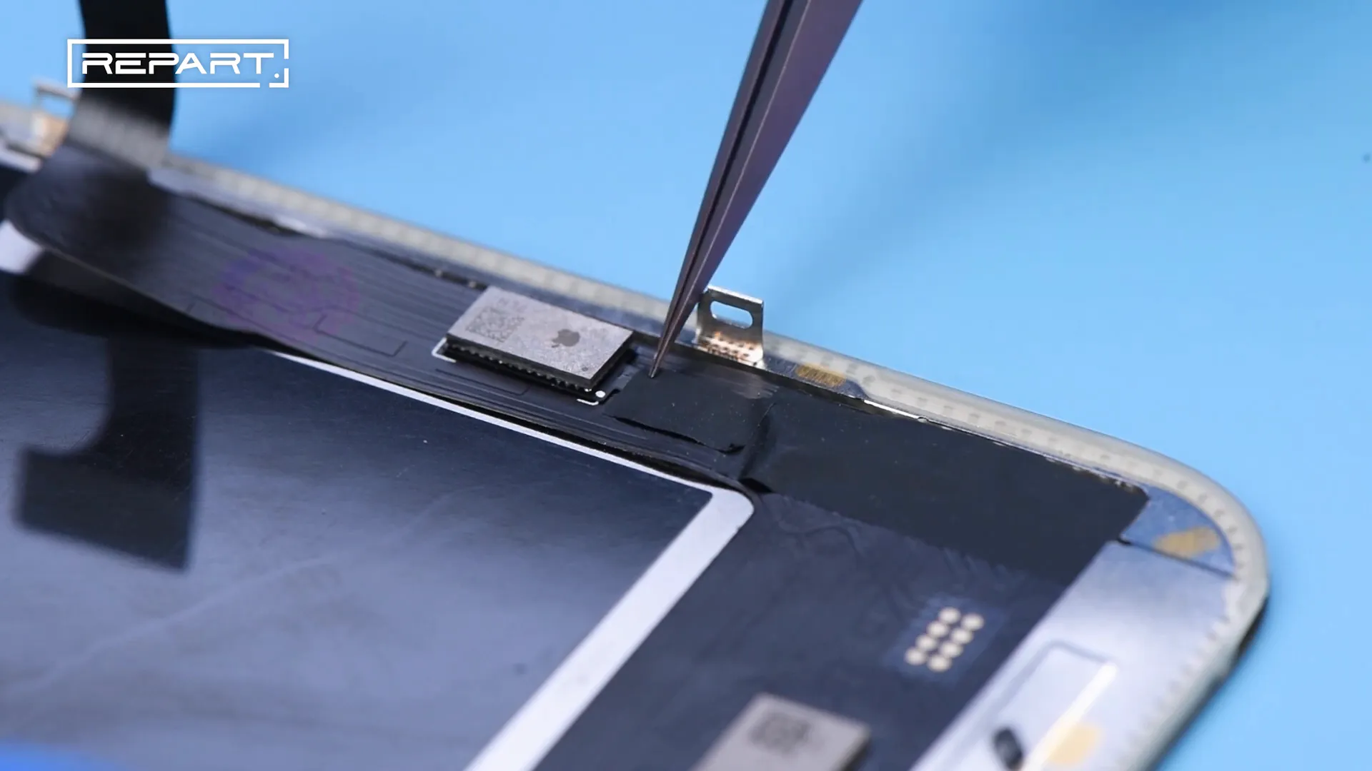
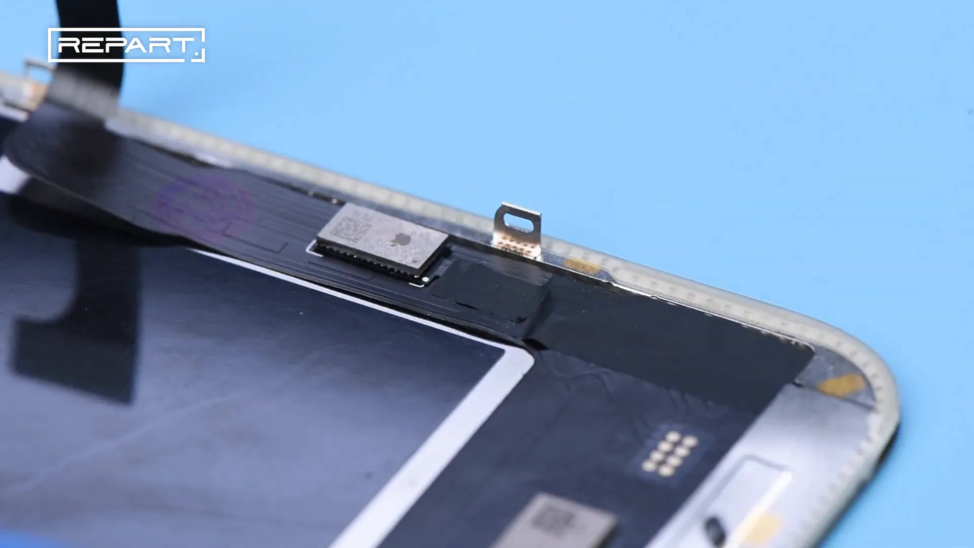
Step 11: Lift the Display Soft Flex Cable on REPART Screen
Carefully lift the display soft flex cable on the REPART screen. This allows access to the solder pads where the additional soft flex cable will be attached.
Step 12: Insert Heat Insulation Pad to Protect the REPART Screen
Insert a heat insulation pad between the screen and the working area to protect the REPART screen from heat damage during soldering.
Step 13: Apply Flux on the Screen's Solder Pads
Apply flux on the solder pads of the REPART screen to prepare for soldering the additional soft flex cable.
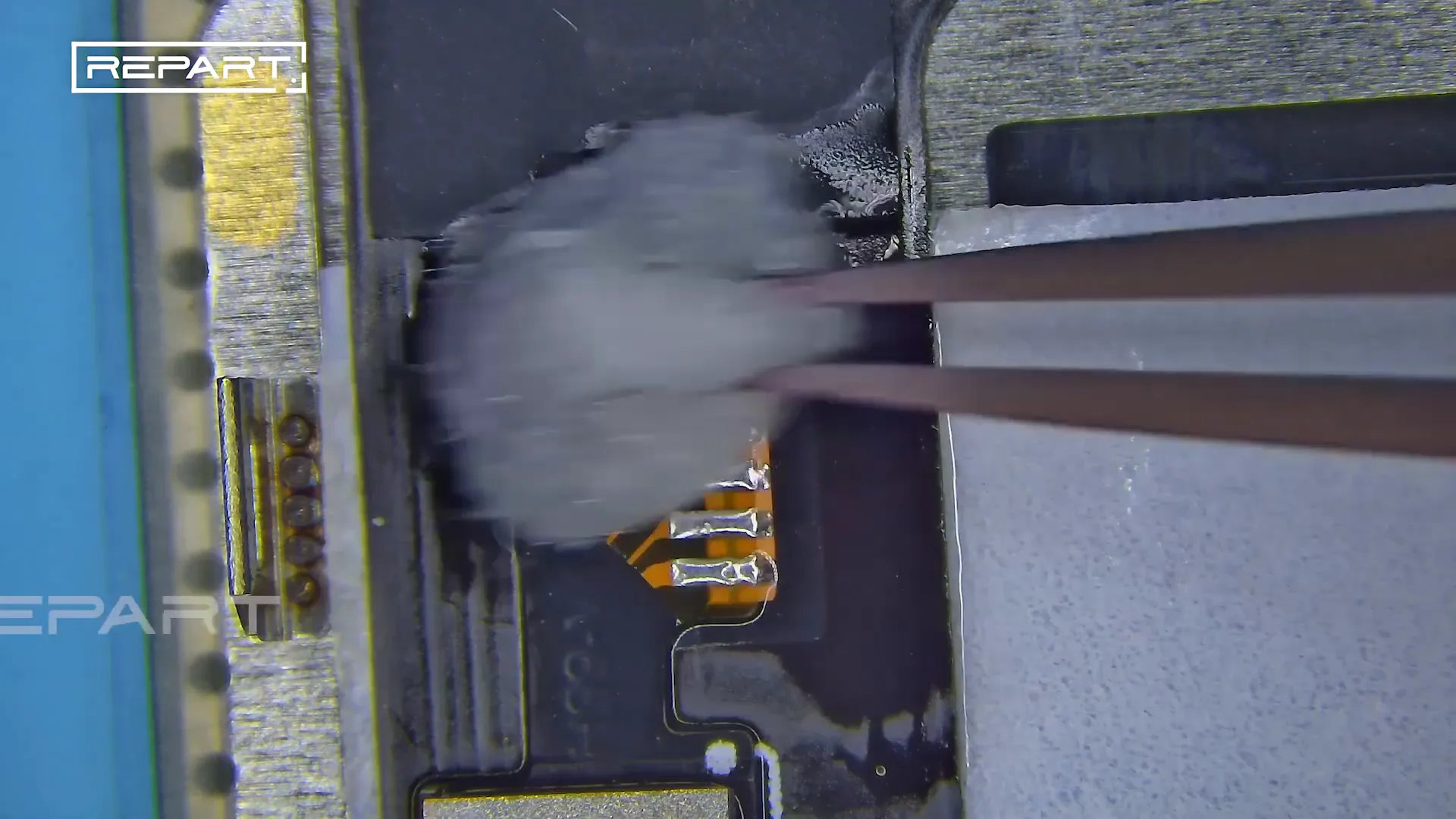
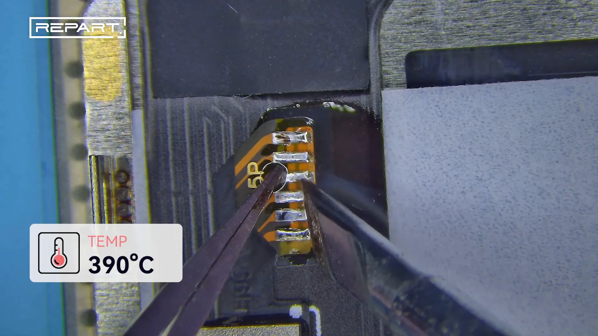
Step 14: Solder the Additional Soft Flex Cable to the Screen
Using a soldering iron heated to 390°C, solder the additional soft flex cable onto the corresponding solder pads on the REPART screen. Precision is essential to avoid bridging or damaging the screen.
Step 15: Clean Residual Flux with Cotton Swab
After soldering, clean any remaining flux residues from the solder joints using a cotton swab dipped in PCB cleaner. This ensures a clean, professional finish.

Step 16: Protect the Soldered Area with Protective Tape
Cover the soldered area with protective tape to secure the connections and prevent accidental damage during further assembly.
Step 17: Install the REPART Screen
Finally, install the REPART screen back onto the device, completing the Screen IC transfer process.
Frequently Asked Questions (FAQ)
Q1: Why is the temperature set to 280°C for the hot air gun?
280°C is an optimal temperature to soften the solder without damaging sensitive components during the reflow process of the IC and soft flex cable.
Q2: What is the purpose of the additional soft flex cable?
The additional soft flex cable is used to transfer the IC from the original screen to the replacement REPART screen, enabling proper pairing and functionality.
Q3: Why do we use medium-temperature solder paste and solder wire?
Medium-temperature solder materials provide a stable melting point that facilitates forming reliable solder joints without overheating delicate parts.
Q4: How do I prevent damage to the REPART screen during soldering?
Using a heat insulation pad protects the screen from excessive heat. Additionally, careful temperature control and precise soldering techniques minimize risk.
Q5: Can this method clear the "unknown part" alert on iPhone screens?
Yes. Proper Screen IC transfer using this method helps clear the "unknown part" alert by ensuring the IC is correctly paired with the replacement screen.
Conclusion
Mastering the Screen IC transfer process is essential for technicians repairing iPhone 13 Pro, 14 Pro, and 15 Pro screens. Following this detailed guide from REPART, with precise temperature controls, flux application, soldering techniques, and protective measures, ensures a successful transfer of the IC and restores full screen functionality. This expertise not only enhances repair quality but also helps technicians meet customer expectations in the evolving iOS environment.
-
Posted in
ic transfer, oled screen

